
Hardware
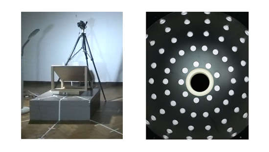
We used two types of capture. Left shows free-form capture using hand-held flash as the illumination source. The right image shows capture using LED lights mounted on a
Near Light Correction for Image Relighting and 3D Shape Recovery
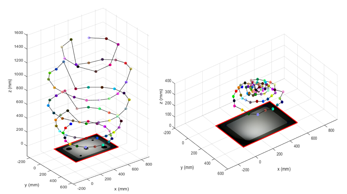 3D Light Position Estimation: A comparison of 3D light position estimation using triangulation from multiple mirror balls (left) and the method proposed in this paper (right). In the left figure, the light positions of 81 dome lights obtained by least square error triangulation from five mirror spheres placed in the center, top left, top right, bottom left, bottom right of the scene. In the right figure, the light positions of the same setup are estimated from just a piece of white matte printing paper. The light positions from the mirror balls are subject to large triangulation errors for lights near the top of the dome. Our technique, however, produces highly accurate estimates of 3D light position. Dataset and Matlab Source Code.
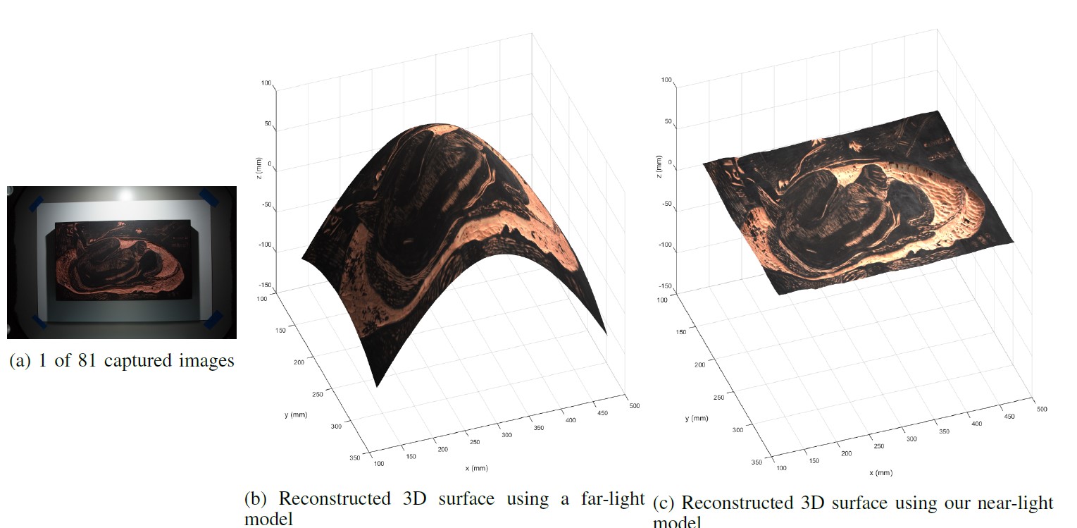
We propose a near-light illumination model for image relighting and 3D shape recovery. We correct the near-light distance effect to provide much more uniformly lit images that yield a more appealing image for relighting applications. Furthermore, we use our near-light model for more accurate photometric stereo calculations of surface normals, eliminating the “potato-chip” shaped surface reconstruction error that results from violating the far-light assumption. We verify our model with both free-form capture using hand-held flash as the illumination source and capture using LED lights mounted on a dome-shaped surface.
We used two types of capture. Left shows free-form capture using hand-held flash as the illumination source. The right image shows capture using LED lights mounted on a
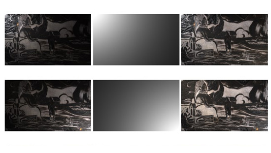
Relighting comparisons for two works by Paul Gauguin housed at the Art Institute of Chicago, a woodblock (top), and a transfer print (bottom). The concession number for the woodblock
is 1940-91, and 2002-237 for the print. A comparison is shown between the raw captured images (left) and after the near-light correction technique introduced in this paper(right). We use the calibrated light position to compute the light attenuation due to the distance squared fall-off. The inverse of this attenuation mask (middle) is used to produce relit images with even illumination (right). The corrected images look uniformly lit and more visually pleasing.
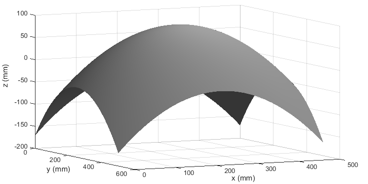
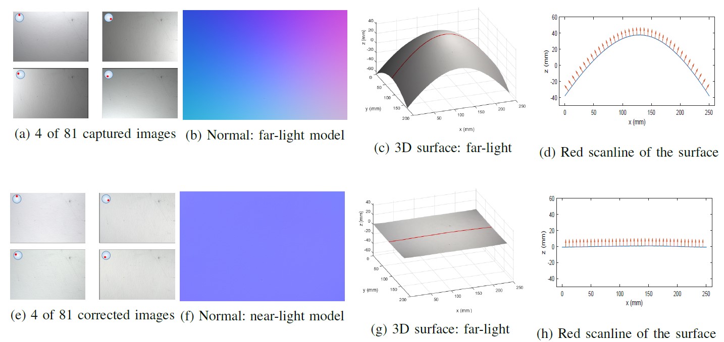
This figure shows the typical "Potato-chip" shaped error resulted from modeling near lights as far lights, which typically occur in the Reflectance Transfer Image (RTI). In this example, the object is 50cm wide, smooth and uniformly flat, and the light is 150cm above the object. The center of the object has an incident illumination angle of 90
degrees, but the left and right border of the central scan line have incident illumination angles of 80.5 degrees and 99.5 degrees respectively, with an error range of 19=2atan(25/150)
degrees from left to right. The erroneous lighting angles cause
Experimental comparison between
Comparison of